Last Updated on May 7, 2022 by Staff
This article is a version of our “Training Chopsticks” design patent as issued by the USPTO, converted to a web-friendly view, for wider dissemination. The issued patent is found as US D933,430 S at USPTO (USD933430S). The specification and accompanying drawings are now in the public domain. And we can now re-upload them to our website without repercussions.
This design patent follows from our utility application on the same, Training Chopsticks – US20210196065A1. This is what we call “model T” training chopsticks, and it is covered in 3D training chopstick models. This design patent documents a 3D-printable model that you can freely print yourselves. See for instance, Model T: Training Marcosticks. Training chopsticks teach learners to not only hold chopsticks with the Standard Grip pose, but also to roll the top chopstick with planetary gear finger motions. These training chopsticks in turns gave birth to our third utility patent application on chopstick buddies: Chopstick Buddies – US2021282579A1.
As we stated in our mission page, we want everyone to be able to print these and even sell them without royalty fees. The patent disclosure establishes prior arts that preempt anyone from claiming these inventions, so no one can stop enthusiasts from freely reproducing these chopstick training tools. With the grant from USPTO, we can now enforce our Mark-and-Go license where we simply ask that folks attribute produced training tools to marcosticks.org.
Cross Reference to Related Applications
This application claims the benefit of my U.S. patent application entitled “Training Chopsticks”, assigned Ser. No. 16/731,037, filed Dec. 31, 2019, which is incorporated by reference herein in its entirety.
Drawing Figures
FIG. 1 is a perspective view showing the front side, the top side, and the right side of my new design, training chopsticks, at the closed posture configuration, with the C-hook coupling bar mounted on the bottom chopstick connecting with the top chopstick via a circumferential groove carved into the top chopstick.
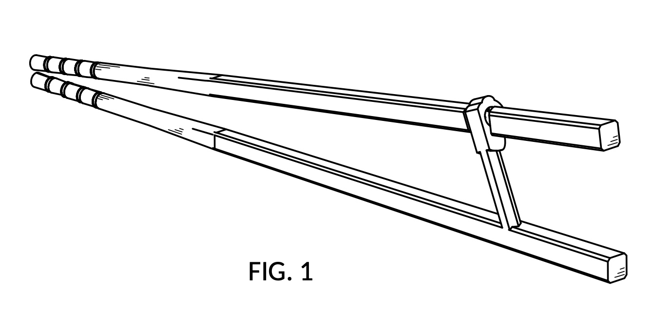
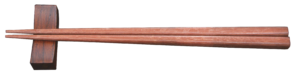
FIG. 2 is a perspective view showing the front side, the top side, and the left side thereof.
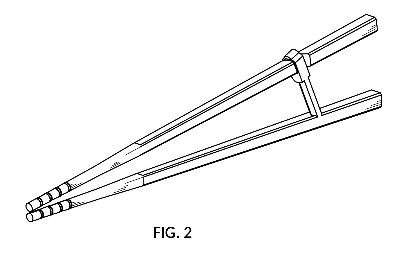
FIG. 3 is a front view thereof.
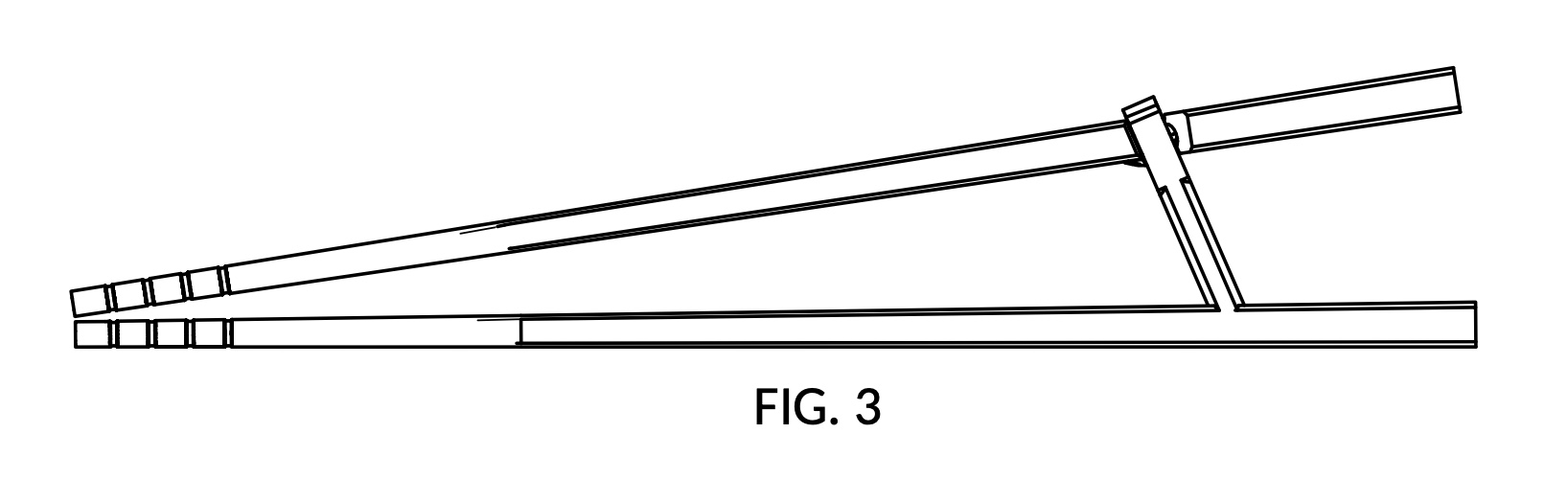
FIG. 4 is a rear view thereof.
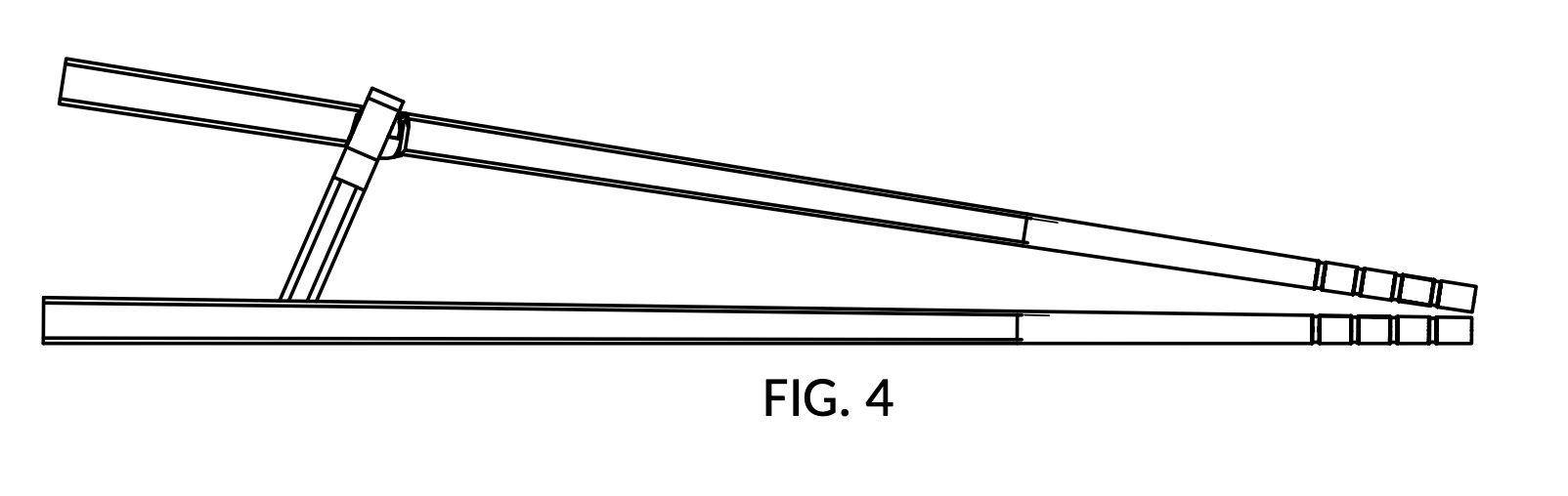
FIG. 5 is a top plan view thereof.
FIG. 6 is a bottom plan view thereof.
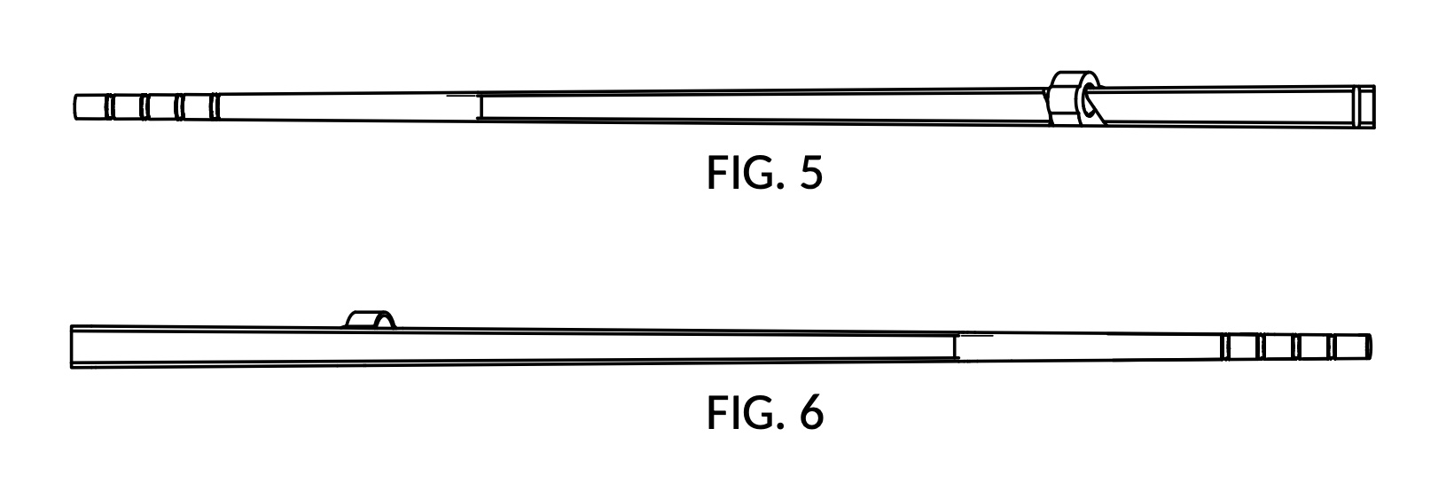
FIG. 7 is a left side view thereof.
FIG. 8 is a right side view thereof.
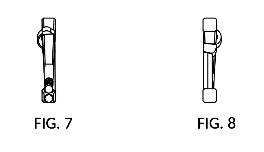
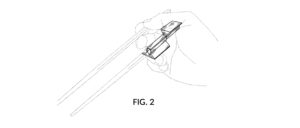
FIG. 9 is a perspective view showing the rear side, the top side, and the right side thereof.
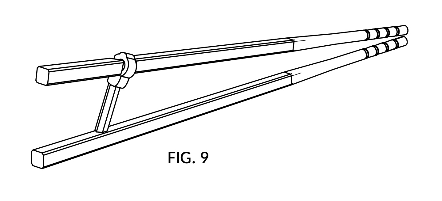
FIG. 10 is a perspective view showing the rear side, the bottom side, and the right side thereof.
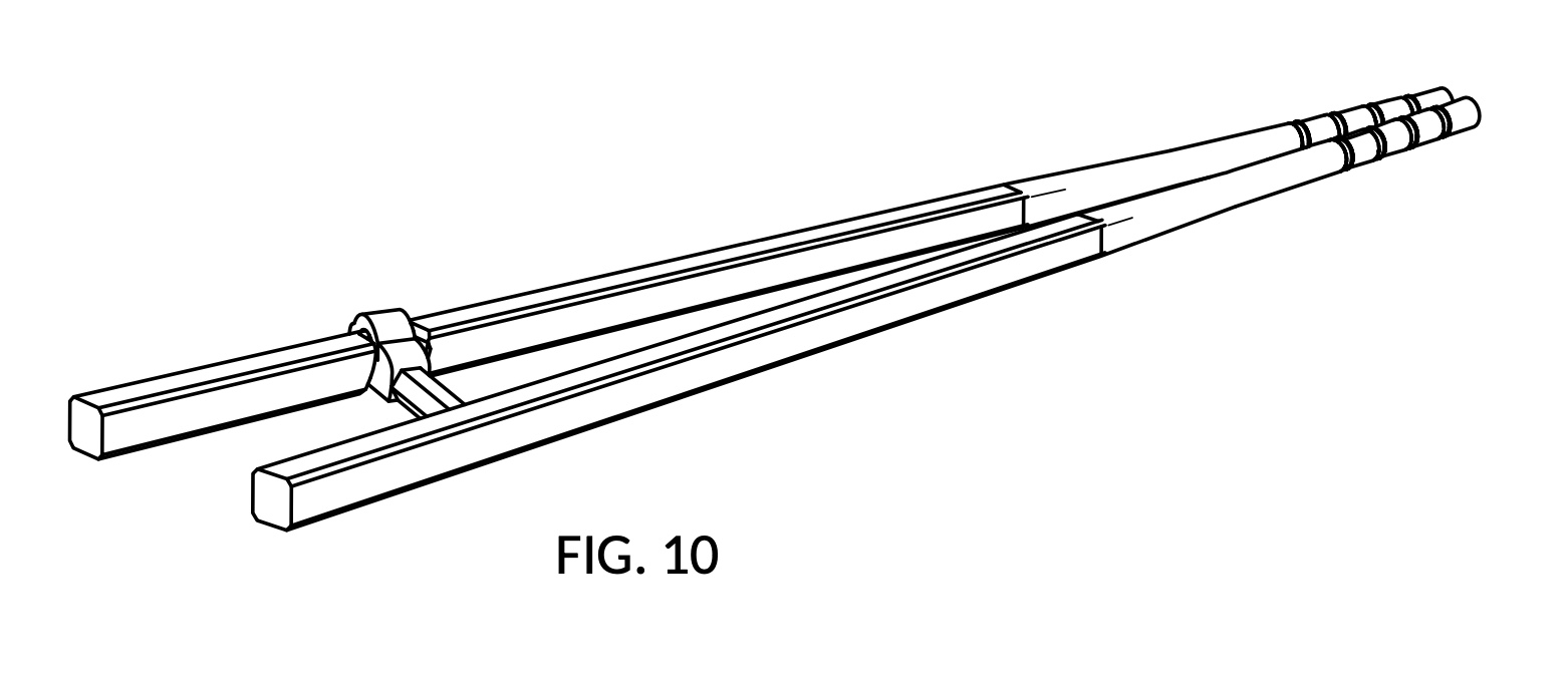
FIG. 11 is a perspective view showing the rear side, the top side, and the left side thereof.
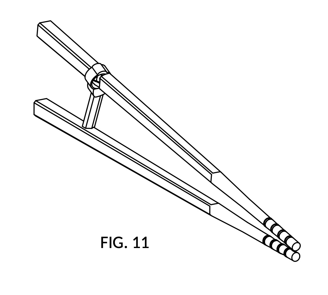
FIG. 12 is a perspective view showing the rear side, the bottom side, and the left side thereof.
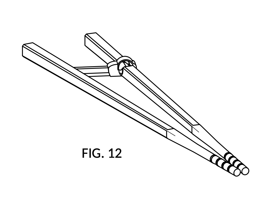
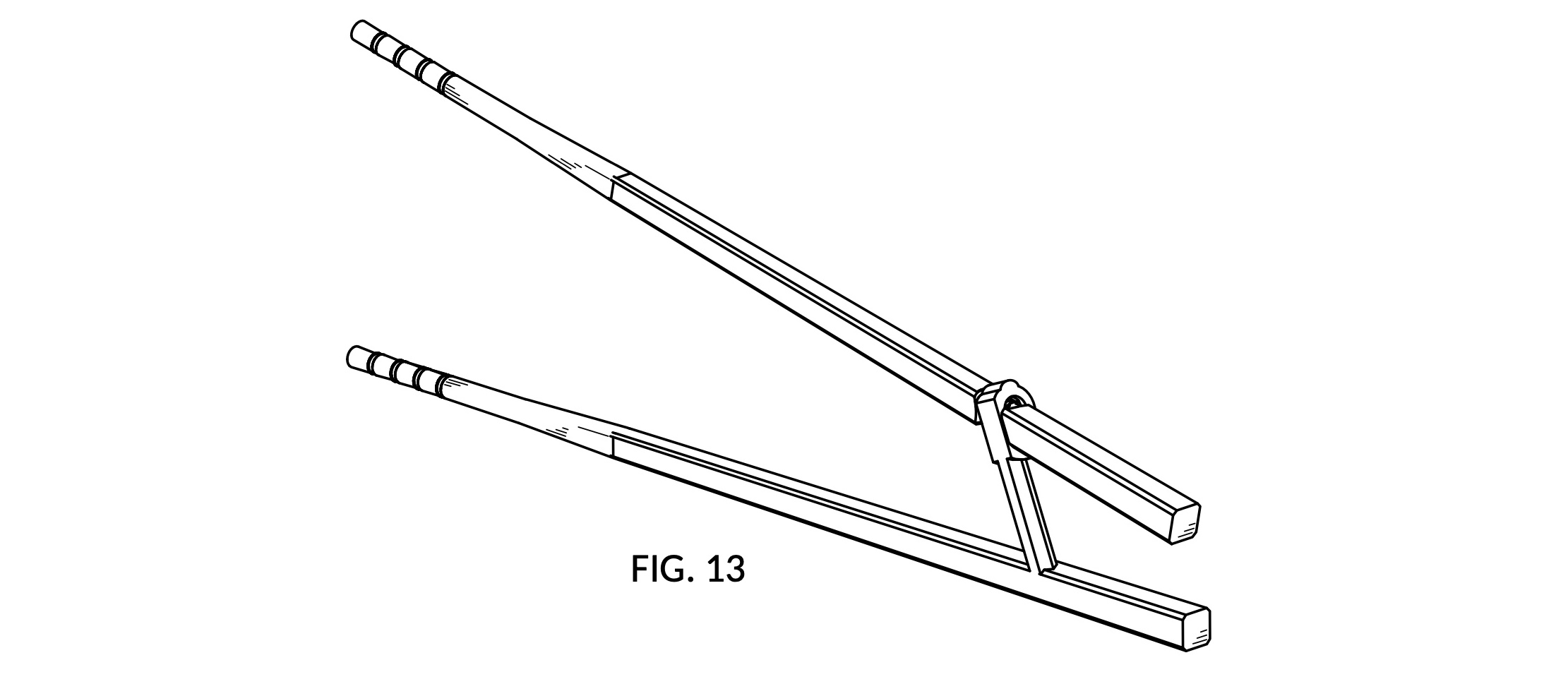
FIG. 13 is a perspective view showing the front side, the top side, and the right side, at another configuration, the open posture, of the training chopsticks.
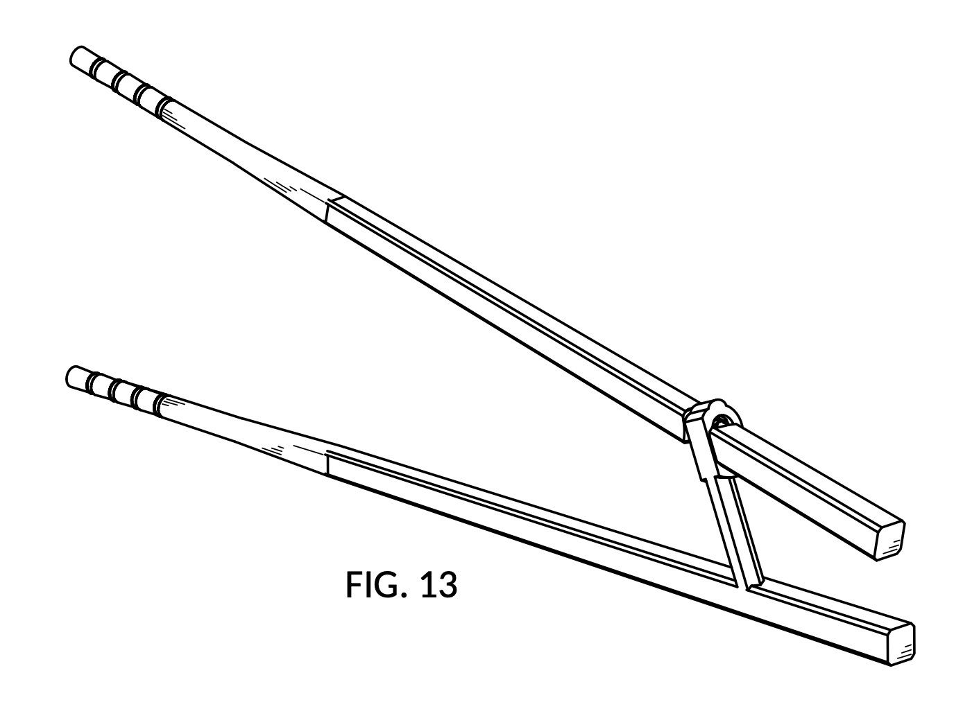
FIG. 14 is a perspective view showing the front side, the top side, and the left side of the training chopsticks in FIG. 13.
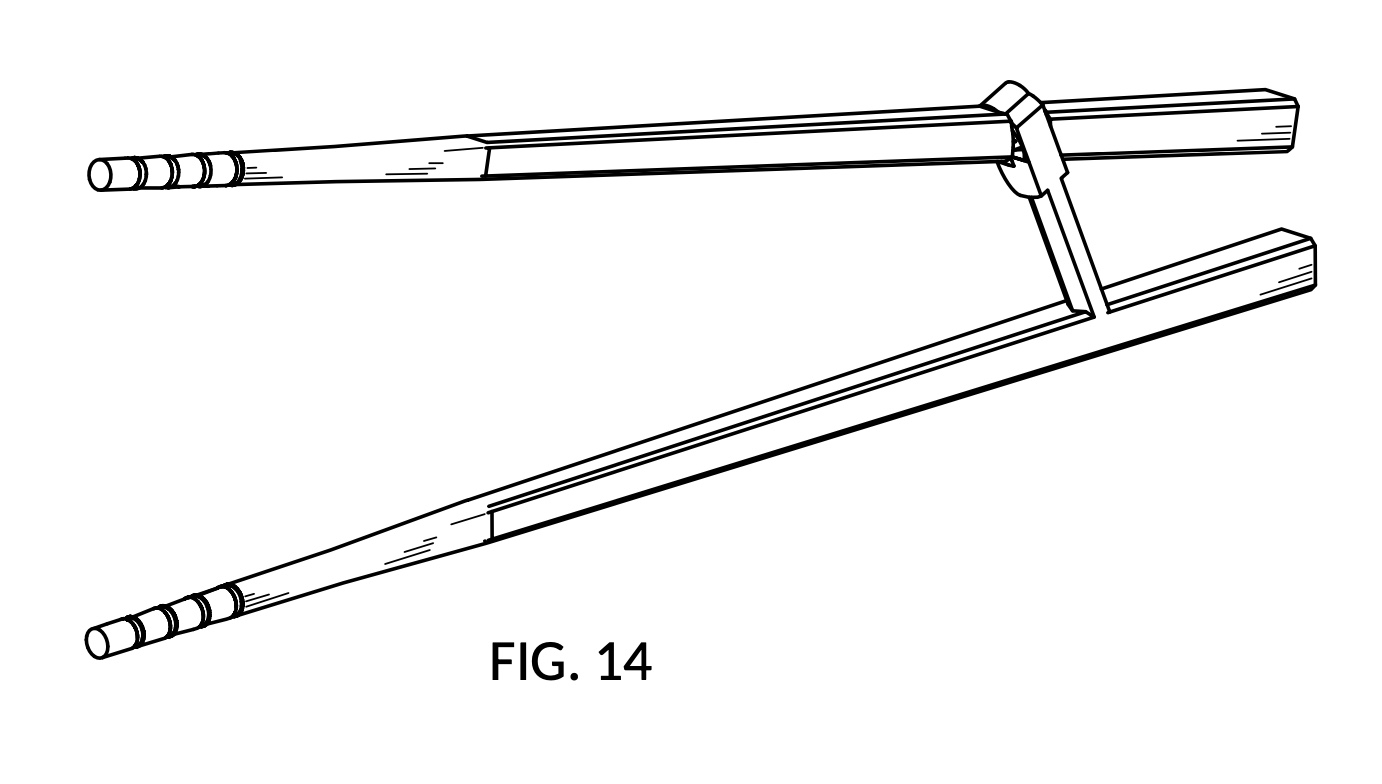
FIG. 15 is a front view of the training chopsticks in FIG. 13.

FIG. 16 is a rear view of the training chopsticks in FIG. 13.
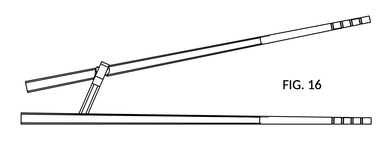
FIG. 17 is a top plan view of the training chopsticks in FIG. 13.
FIG. 18 is a bottom plan view of the training chopsticks in FIG. 13.
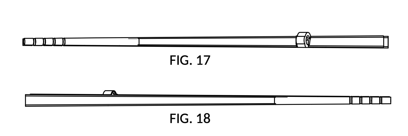
FIG. 19 is a left side view of the training chopsticks in FIG. 13.
FIG. 20 is a right side view of the training chopsticks in FIG. 13.
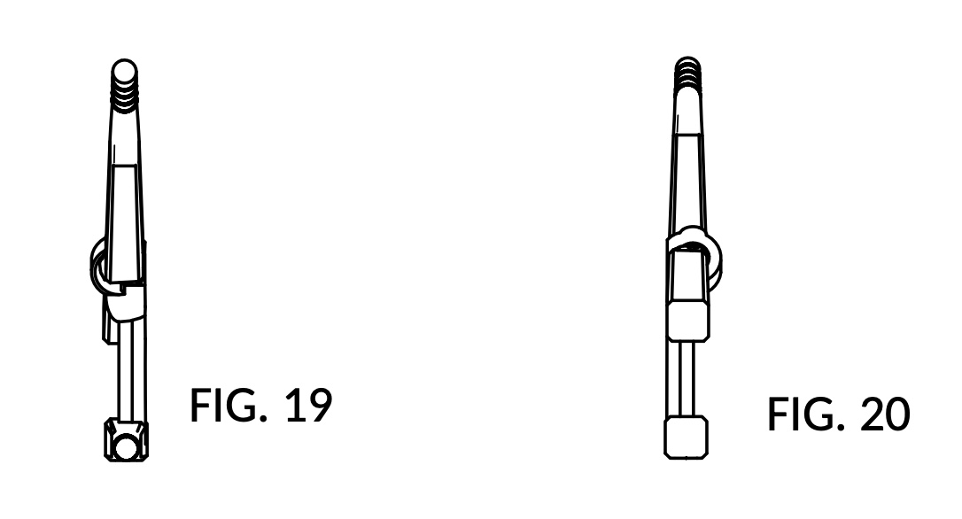
FIG. 21 is a perspective view showing the rear side, the top side, and the right side of the training chopsticks in FIG. 13.
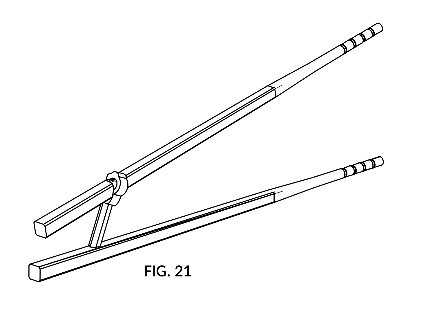
FIG. 22 is a perspective view showing the rear side, the bottom side, and the right side of the training chopsticks in FIG. 13.
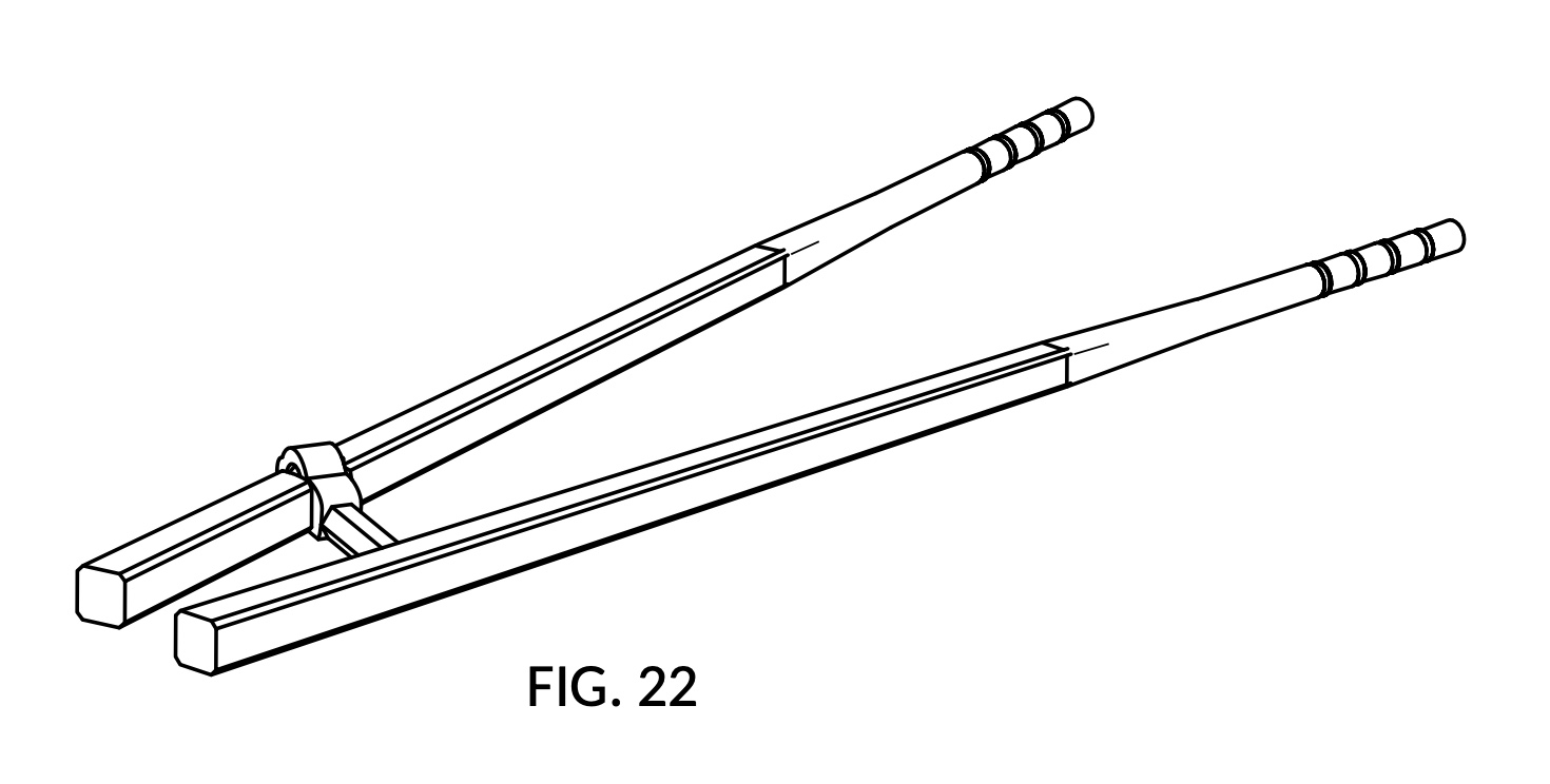
FIG. 23 is a perspective view showing the rear side, the top side, and the left side of the training chopsticks in FIG. 13
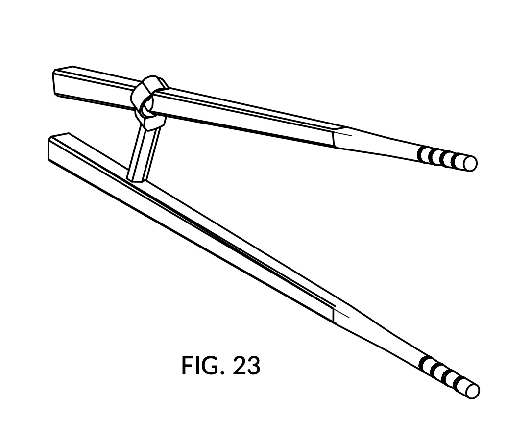
FIG. 24 is a perspective view showing the rear side, the bottom side, and the left side of the training chopsticks in FIG. 13.
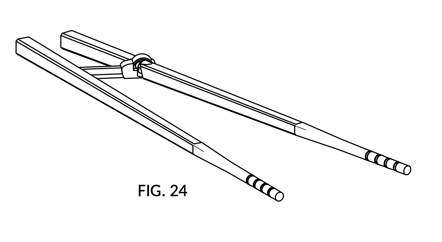
FIG. 25 is an exploded view of a portion of the training chopsticks, including the C-hook coupling bar, and the exposed circumferential groove carved into the top chopstick, in a perspective view showing the front side, the top side, and the right side.
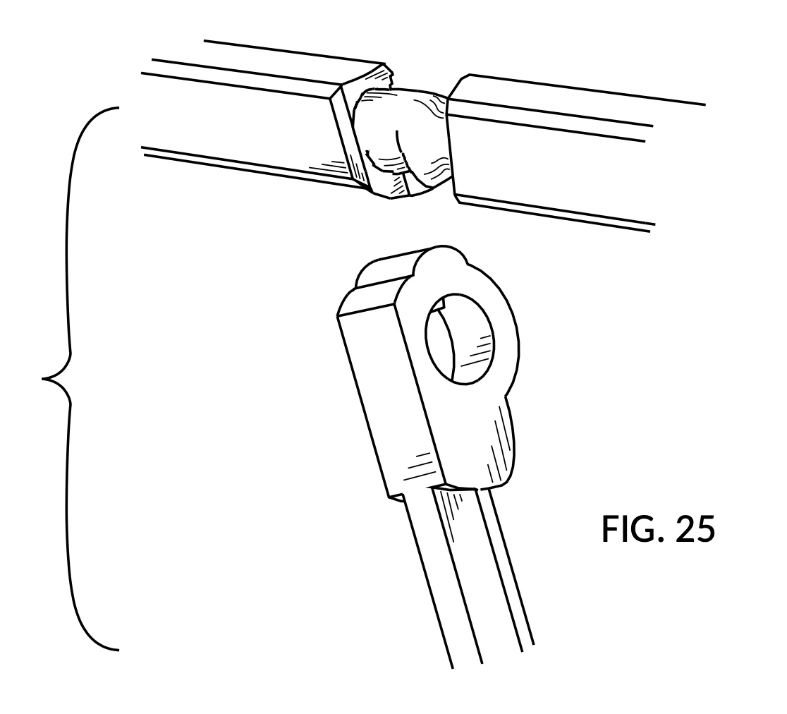
FIG. 26 is a perspective view exploded portion in FIG. 25.
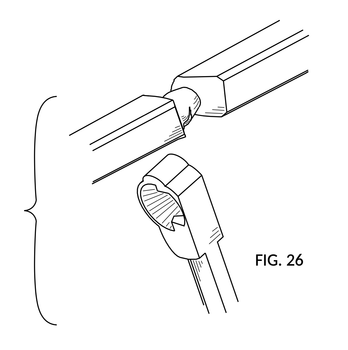
FIG. 27 is a perspective view exploded portion in FIG. 25.
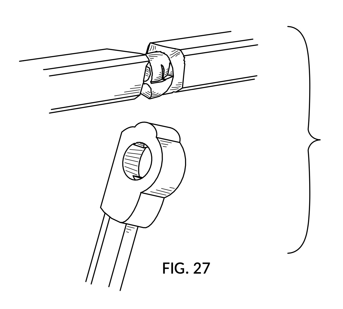
FIG. 28 is a perspective view showing the rear side, the bottom side, and the right side of the exploded portion in FIG 25.
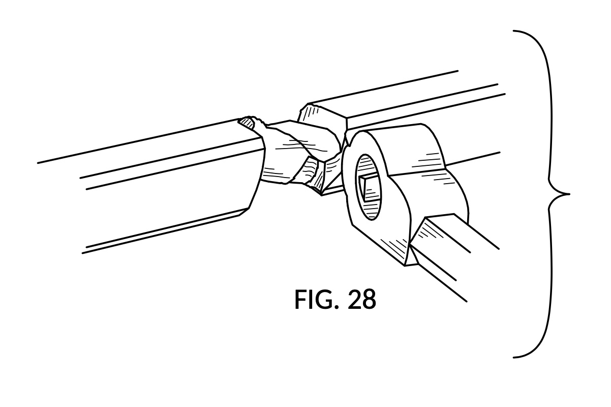
FIG. 29 is a perspective view showing the rear side, the top side, and the left side of the exploded portion in FIG. 25.
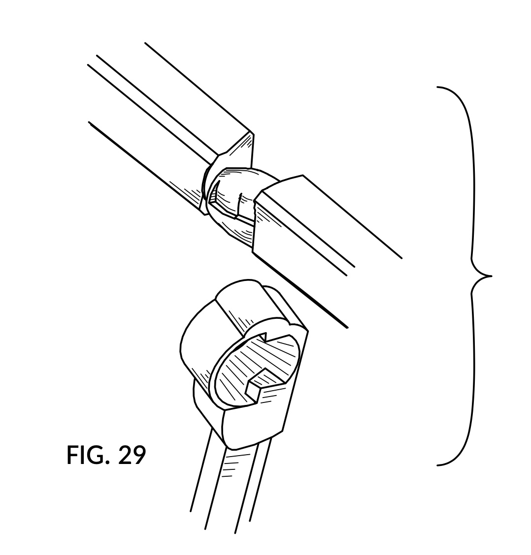
FIG. 30 is a perspective view showing the rear side, the bottom side, and the left side of the exploded portion in FIG. 25.
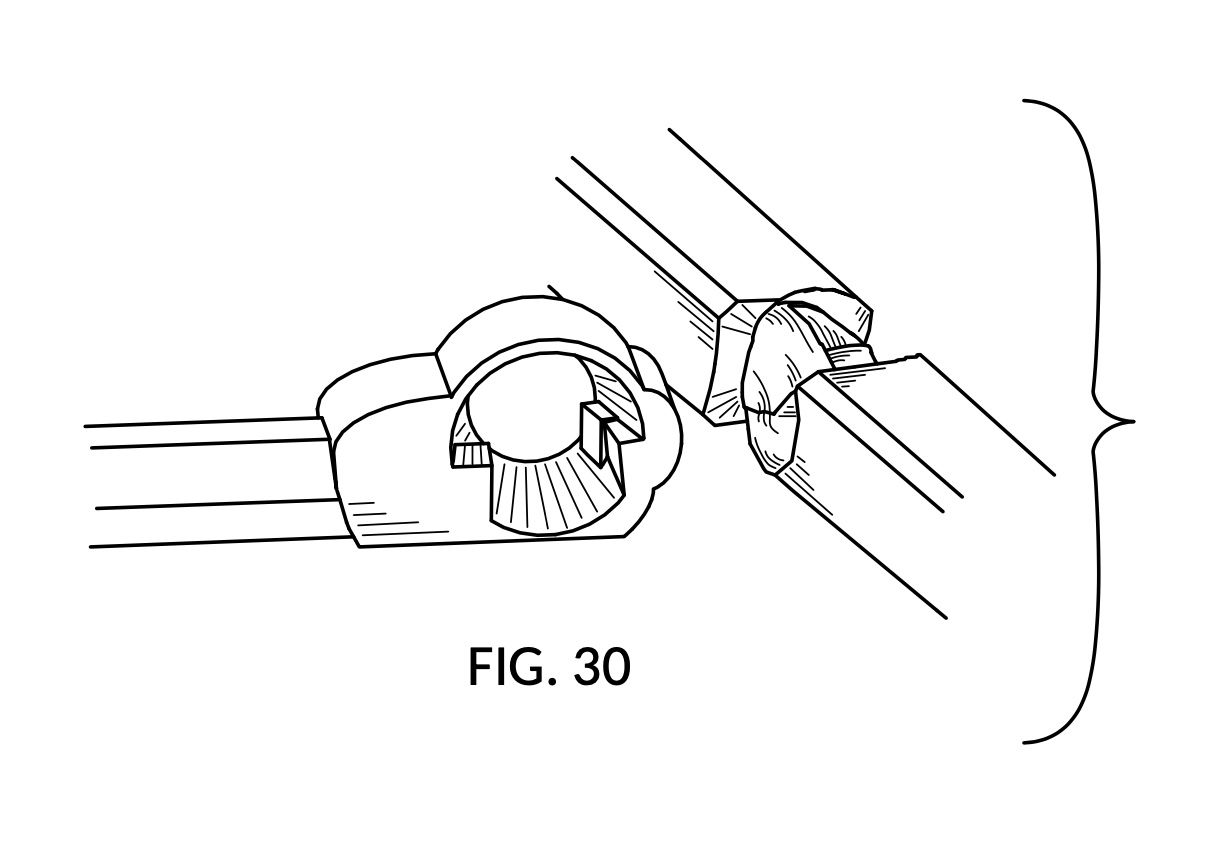
FIG. 31 is a front view of the exposed circumferential groove carved into the top chopstick shown in the exploded view in FIG. 25.
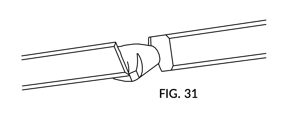
FIG. 32 is a rear view of the exposed circumferential groove in FIG. 31.
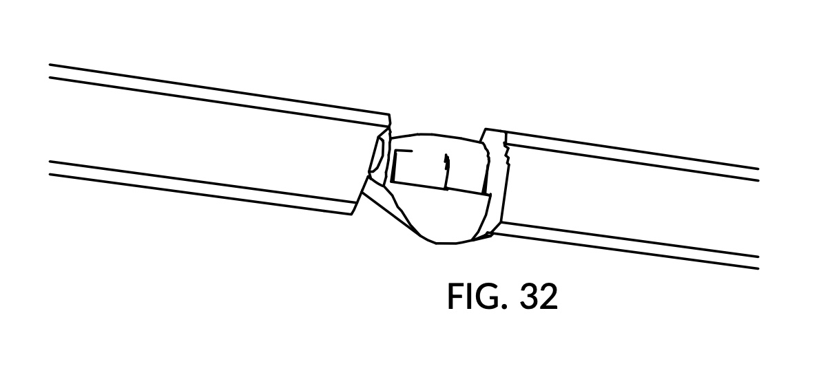
FIG. 33 is a top plan view of the exposed circumferential groove in FIG. 31.
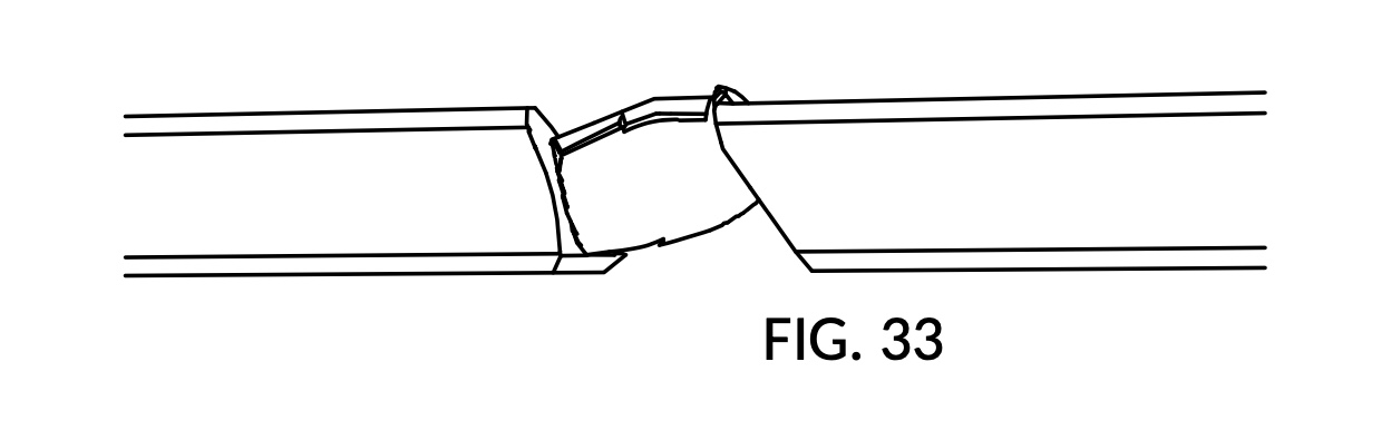
FIG. 34 is a bottom plan view of the exposed circumferential groove in FIG. 31.
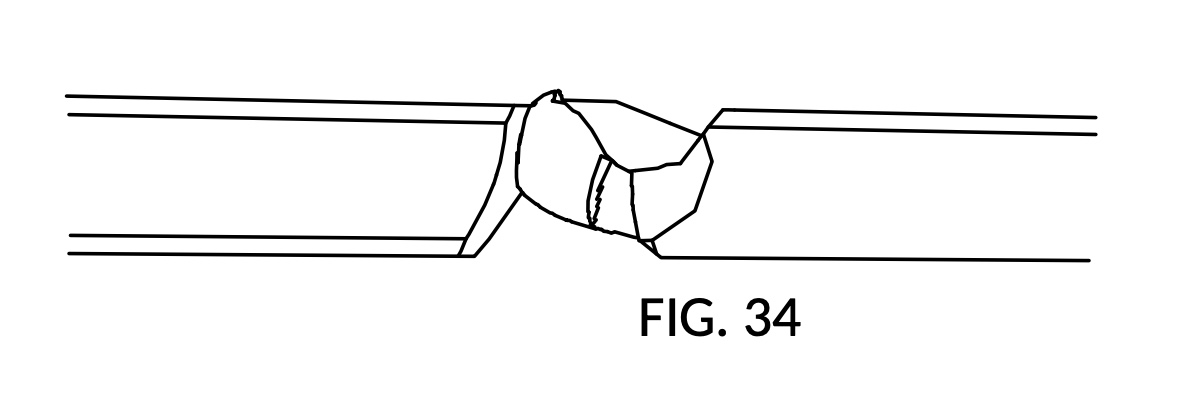
FIG. 35 is a front view of the C-hook coupling bar shown in the exploded view in FIG. 25.
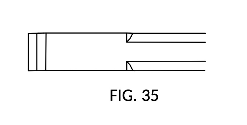
FIG. 36 is a rear view of the C-hook coupling bar in FIG. 35.
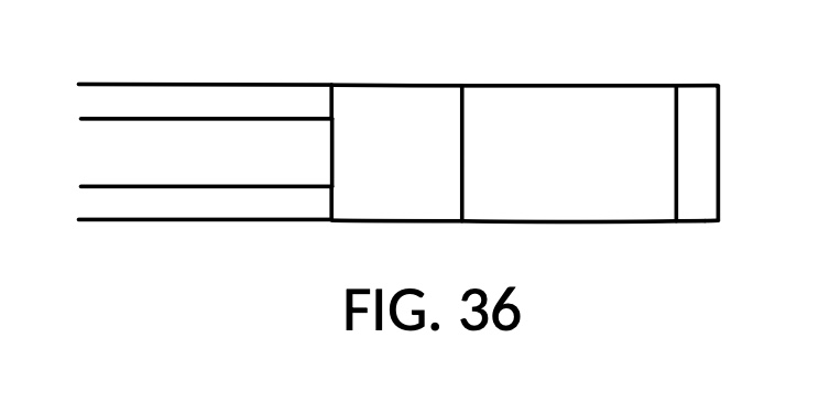
FIG. 37 is a top plan view of the C-hook coupling bar in FIG. 35.
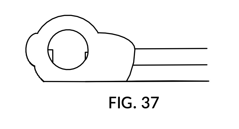
FIG. 38 is a bottom plan view of the C-hook coupling bar in FIG. 35.
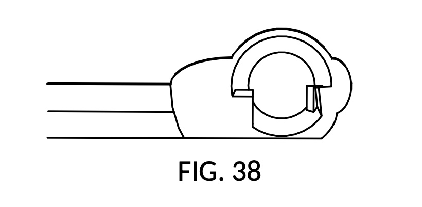
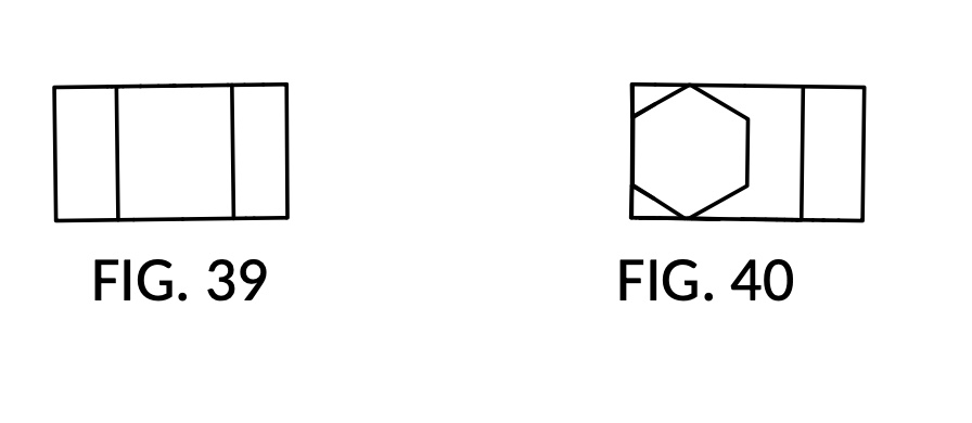
FIG. 39 is a left side view of the C-hook coupling bar in FIG. 35.
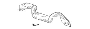
FIG. 40 is a right side view of the C-hook coupling bar in FIG. 35.